

Cabling schematic plans
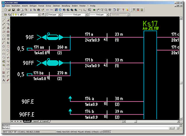
The cable overview plan presents the connection of safety-relevant elements to the signal box and the required cables in schematic form. Cabling-relevant properties of the elements which must be connected depend on the selected type of signal box. During cable determination ProSig®establishes the most cost-effective cable type, subject to compliance with electrical limit values, thus achieving cost savings.
- Insertion of cable cabinets, ring feeders and cable fanouts
- Automatic takeover of elements which must be cabled from the layout and overview plan into the cable overview plan
- Completeness check through by matching the signal plan and the cable overview plan regarding the elements which must be cabled
- Use of project-specific cable catalogues
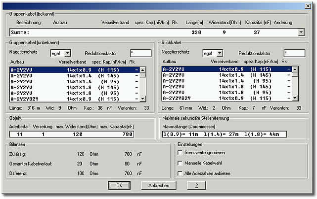
- Inclusion of service cables with automatic determination of required cores and cable type, depending on the signal box
- Inclusion of group cables with automatic determination of required cores and cable type
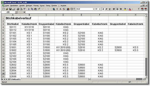
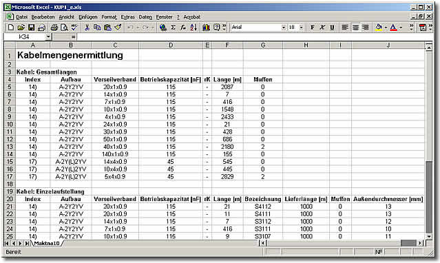
Extensive evaluation functions determine the overall lengths and create an itemised listing of cables used. The core route of all cabled elements up to the signal box is presented in a tabular overview.
- Determination of cable lengths, approximated from the signal overview plan or by determination of the cable route from the signal layout plan Consideration of defective cable cores
- Differentiation between physically existing cables and planned cables
- Determination of the number of cable cabinet terminals with automatic tracing in case of changes of service cables or group cables
- Display of the cable route
- Output of cable cabinet overview plans
- Fully automatic determination of cable quantities
- Output of the cable route